Basics of Tangent Drive
July 21, 2025
What is Tangent Drive?
Most combat robot drivetrains get their power from a pair of gearmotors, one per side of the drive. These motors typically drive the wheels using belt+pullies, gears, or through a direct motor mount (as seen in my beetleweight spinny boiii). Tangent drive, on the other hand, is a less traditional strategy that uses the motor shaft (typically without a gearbox) to drive the edges of the wheels through rolling friction. This method is becoming more popular among builders because of its simplicity and relatively low cost.
Driving wheels through friction at the edge of the tire results in some interesting properties that can be very useful for certain robot designs. This drivetrain option is not without its challenges, but it is more accessible than ever due to the availability of small, power-dense drone motors and AM32 ESCs with good low-speed performance.
How Big Should My Wheels Be?
This question leads us to the main interesting property of tangent drive setups. We’ll explore this through comparison.
Direct-Drive Setup
Let’s first consider a more traditional, direct-drive setup where a gearmotor directly applies power to a wheel. The linear speed and force produced by this wheel (assuming no slip and perfectly efficient torque transfer) is given by the following:
Where:
- is the linear speed of the robot
- is the linear force the wheel applies to the ground
- is the radius of the wheel
- is the angular velocity of the motor (rad/s)
- is the torque produced by the motor
- is the gear ratio of the gearbox
From these equations, it is clear that the wheel size affects the speed and force of the drivetrain. If all else is kept constant, increasing the wheel size will gain speed and lose force, while reducing wheel size will lose speed and gain force.
Tangent Drive Setup
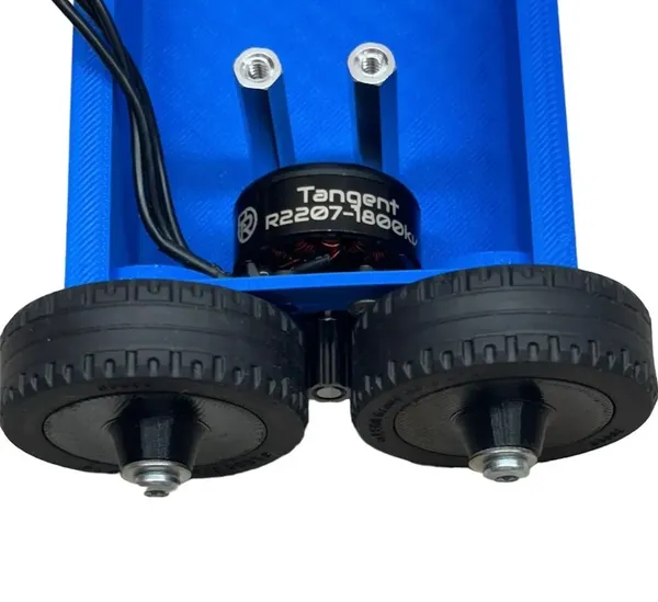
Now consider a tangent drive setup, where the motor shaft drives the edge of the wheel through friction. The motor has no gearbox, but the rolling contact creates a gear ratio that depends on the wheel radius and the motor shaft radius (i.e. , where is the motor shaft radius). Making this substitution and applying the same assumptions as before, the linear speed and force produced by this wheel is:
We can see that the term has been canceled out because the gear ratio of the system depends on the wheel radius. For tangent drive systems, the wheel size has no impact on the robot’s ground speed and available pushing power!
Design Considerations
Because of the wheel size irrelevance and the nature of the rolling friction contact, there are some important trade-offs to consider when designing a robot with tangent drive.
1. Susceptible to motor shaft slippage
Tangent drive is more liable to slip than other options, so the design needs to carefully position the motor relative to the wheel to obtain good engagement. For example, the 2207.5 Repeat Tangent Drive Motors recommend 0.8mm - 1.2mm of interference between the motor shaft and the wheel, depending on the wheel design. Importantly, most of these designs use 2 wheels engaging with each motor shaft, which can effectively prevent the motor shaft from tilting away from a wheel and disengaging. Using tangent drive on 2-wheel robots can be more finicky because of this, though using a small idler wheel or a sufficiently stiff motor+wheel mount can help.
2. Relatively short drivebase
Most tangent drive robots use a fairly small drive shaft, which means the front and back wheels end up relatively close to one another. This drivebase length is often shorter than that of many typical 4-wheel-drive robots. You can still use tangent drive motors with belts/pullies to extend the drivebase, but this adds complexity and may introduce slippage as discussed previously.
3. Less control over the robot’s final speed and torque
Wheel size is no longer an important factor in the robot’s drive performance, and that means one less lever to pull. If you want to adjust the speed or torque your robot has, you’ll have to make those changes by choosing motors with more speed or torque, and by changing the shaft size. This may be more difficult than adjusting the wheel size, though newer tangent drive products likely cover most beetleweight and antweight use cases.
4. Greater design freedom!
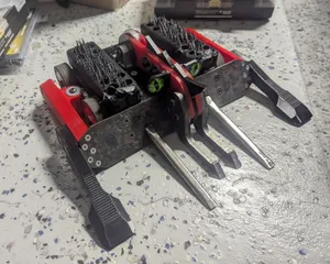
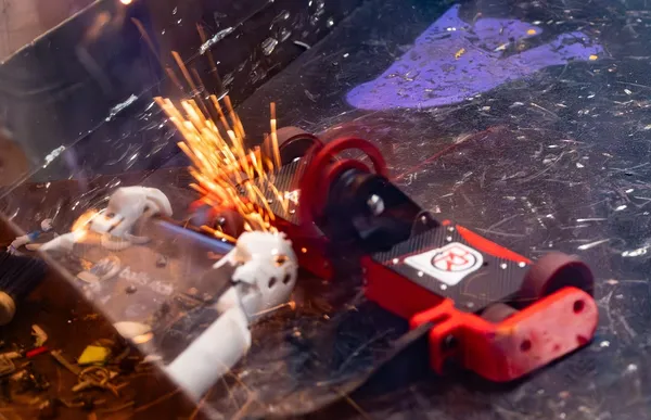
On the flip side, tangent drive robots are free to size their wheels to best fit the rest of the design without worrying about its impact on speed or pushing power. The front and back wheels do not even have to be the same size! This is possible with gears and belt/pulley as well, but the tangent drive approach requires fewer components and is more compact. The beetleweight robot Z3phyr (shown below) is a good example of this tangent drive strategy, using small front wheels for greater protection and larger rear wheels to improve mobility and avoid getting stuck on its back.
Conclusion
Tangent drive provides some notable design advantages and caveats, and it can enable some really interesting designs. The following table summarizes the pros and cons of tangent drive discussed in this post. Personally, I think it is a compelling approach and will seriously consider it for my next robot design!
| Pros | Cons |
|---|---|
| Wheel size does not affect speed or pushing power, allowing more design freedom | More susceptible to slippage; careful alignment and interference needed |
| Simpler, more compact drivetrain (fewer components) | Less control over speed/torque via wheel size; must select motor/shaft carefully |
| Can use asymmetric wheel sizes for protection or mobility | Shorter drivebase (front/back wheels close together) unless using belts/pulleys |
| Lower cost and lighter weight | Can be tricky to implement on 2-wheel robots due to disengagement risk |
| Enables creative layouts and packaging | May require stiffer mounts or idler wheels if only 1 wheel per side is friction-driven |